There seems to be a lot of confusion over what you can and can't do with the combination of Lightwave and Zbrush on the net, so I thought I'd write this tutorial to try and clear some of that up. I've been using Zbrush with Lightwave for a couple of months now and this is what I understand to be accurate. I'm going to take you through th steps of having a mesh in Lightwave and taking it into Zbrush and displacing it there, and then applying that displacement back in Lightwave. You'll need to be a little familiar with Lightwave, and have to explore Zbrush on your own, though I do run through some of the basics.
Step 1: The Lightwave mesh.
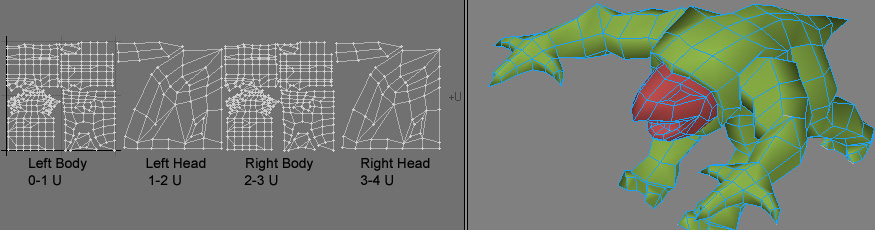
I don't tend to use the modelling tools in zbrush like zspheres, although they're fairly complete, since they lack one or two features I use in LW and I find I can make up a rough low polygon object in LW much faster than in Zbrush having used it for so long. I also like to use the UV tools in LW to make my map, so that it's as optimal as I can make it, and as understandable as I can make it. I find the auto UV maps made in Zbrush tend to have a lot of seams, and aren't laid out to make it easy for me to paint on should I go into photoshop afterwards. So I've made my object in LW, and I've split the head from the body in UV space, the body being in 0-1 U and the head being in 1-2 U. This means I can have a higher resolution displacement map for the face, since you'll be looking at it the most. I'm going to use the same displacement map and colour map for each half, so they're symmetrical, therefore I've split the object along the y-z plane, and moved the right side parts out to 2-3 and 3-4 in the U. I've called the body surface 1_BodyLeft and the head surface 2_HeadLeft and so on. When Zbrush outputs the displacement maps, it'll use 1,2 etc as suffixes for each UV segment, 1 for the segment 0-1, 2 for segment 1-2, 3 for 2-3 and so on in U. Naming our surfaces like this is more useful when you have a lot of segments, so you can keep track of which displacement map .tif (the filetype Zbrush uses) goes where later on.
Also, by grouping polygons of your object together by using the View>Selection Sets>Create Part function in Lightwave (for example Arms, Legs, Body, Head) these will be exported in your .obj file (this is the file type Zbrush uses for polygon objects). Zbrush will pick these up as Groups (how it groups polygons together), and it will make it easier to hide parts of your object when you're painting complex parts.
Step 2:Exporting to Zbrush
Once you have your mesh laid out as you want it, you have to save as a .obj. You do this by using File>Export>Export OBJ. Some things to take note of are:
Step 3: Importing in Zbrush
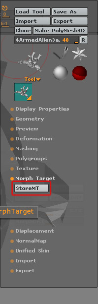
Go to Tool>Import and select your exported .obj. Click and drag in the main viewport, and you'll see the object being drawn. It'll be upside down, but if you drag around, you should be able to right it. Immediately click the Edit button at the top of the window, and you'll be able to paint and modify it. Click the Frame button, and you'll see the mesh coloured according to the groups you have set up on your object. Also, it's important to store a morph target (Tool>Morphs>Store MT) at this point, as Zbrush uses this to determine where the mesh has been displaced and generate the displacement/Normal maps later on.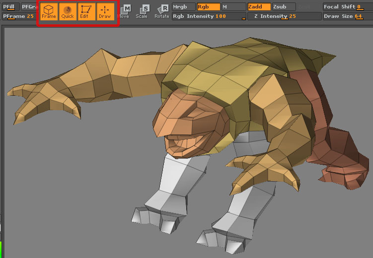
Step 4: Working in Zbrush
From here you'll have to learn how to use Zbrush, but some useful tips are:- Holding the Ctrl button while holding your cursor over a menu item will give you a useful description of that function.
- Click-dragging anywhere in the view except on the object will rotate it. Alt-Dragging in the window except on the object will move it. If you want to zoom, you hold down Alt, click and hold the left mouse button then release the Alt button, and drag, and you can zoom in and out.
- Ctrl-d will subdivide your object to make it smoother so you can paint your deformations. You can keep doing it till you hit your poly limit (set in the Prefs>Mem>Maxpoly per mesh). Once it's subdivided, you can go down the subdivision levels to more basic by pressing shift-d and go back up to smoother by pressing 'd'.
- You can save your work by going to Tool>SaveAs and save it as a .ztl file. This will save your images, any alphas and the deformations on the tool in the one file, so it's nice and easy and USEFUL to do this regularly.
- There are two main modes in Zbrush for painting on 3d objects. Tool modification mode, and Projection Master mode.
- Since you've brought your object as a tool, using the Draw/Move/Rotate/Scale buttons in Tool modification mode will paint only on your mesh. You can rotate around your mesh in this mode. You can't use any other types of brush on it, just an airbrush type brush. You can also paint different Materials on your mesh, but these are on a per polygon basis, so the higher the subdivisions on your object, the more precise the material can be painted.
- You can also paint Colours (You'll need to create a Texture for this) on your mesh. The material can be saved (kind of) as an alpha image.
- You have 10 different brush effects you can do, these are found in the Transform Menu :
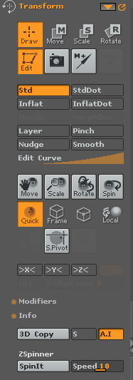
- Std - bulges the surface along the average normal of the faces.
- std dot -makes a dot which you can move around till you're happy, then leave on the surface.
- Inflat - bulges the surface along the normal of each face.
- Inflat dot - like std dot, but using the inflate method.
- Morph - paint back to the morph target
- Morph dot
- Layer - paint a layer which is smooth and level till you lift the brush and start painting again.
- Pinch - useful for wrinkles, but not suitable for displacements as it moves adjacent faces towards each other, not up or down.
- Nudge - again, pushes poly around, so not really suitable for displacement painting.
- Smooth - Smooths out deformations.
- You can also activate symmetry for your strokes, by clicking the >X<,>Y<,>Z< buttons, or pressing the keys x,y or z.
- You can invert the effect a brush has by pressing alt and drawing on the mesh.
- If you hold down shift while drawing, this turns the tool into the smooth tool. You can reconfigure this by pressing shift and clicking one of the other tools.
- To enter Projection master mode, press g to bring up the Projection master panel.
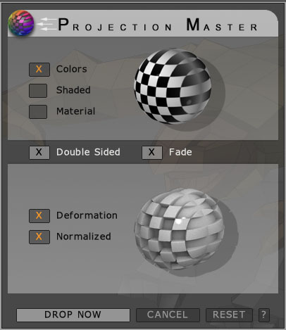
This will basically 'Drop' your object onto the canvas and you'll be able to use other brush types on it, but not to move or rotate it. If you want to paint colours on your object in this mode, you will also need an image assigned to your object before you go into the mode. You can make one in zbrush or load one you've made already. Once you've finished modifying your object, you'll be able to pick up your object again (press g), and continue in tool modification mode. Which boxes are ticked in PM mode will determine what lasting effects you have on your mesh, and Zbrush gives you a preview of what will happen on the spheres as you toggle the features on and off.
Step 5: The Multi Displacement Panel
Now you've painted your object's deformations, it's time to export your
deformations. First of all,
use shift-d to reduce your object down to it's lowest subdivision
level, just like it came in. ZB needs to be in this mode so it can
calculate the displacements from the base mesh. We're going to use the
Multi Displacement 2 exporter,
which is downloadable from www.pixelogic.com . You install it to
ZBrush2\ZStartup\Zplugs, and it comes up in the interface at
Zplugin>Mulidisplacement 2.You'll need to
restart Zbrush first for it to see these plugins. There are 3 buttons,
one for finding out how many segments the object
has, one for creating all the maps, overwriting any old ones, and one
for just creating new maps. The settings below those buttons are fairly
self explanatory, and then there's the Export Options.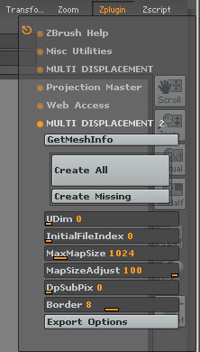
Step 6: Exporter options
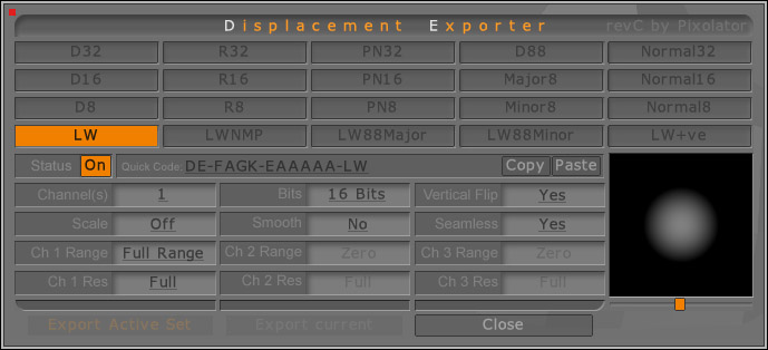
This panel is quite important for setting how the displacement images are made, so there are a few things to note. Zbrush comes with a whole array of presets, which will give different images. Each 3d package handles displacements slightly differently, so you have to pick the settings to match your package. Also, when you use a function which uses the Displacement Exporter panel (you can use it in the Alpha panel as well) when you export, Zbrush will export images for each preset which has its status set to ON. These presets will be highlighted in orange. For this tutorial I'm just going to be exporting one 16 bit image for each section of my object, so I have my base LW exporter as the only one on. Also, Zbrush converts the settings to a 'Quick' code which you can see above, and if you want to share this with a friend, you just type in the quick code and it will set up the preset for them. The last part of the quick code is the name of the preset.
Anyway, the settings are as follows.
- Channels - determines whether 1 channel (greyscale) or 3 (RGB) is used for the texture. 1 is usually used for displacements, and 3 for Normal maps.
- Bits - no of bits per channel. Usually 16 for displacements to give better accuracy, and 8 for normal maps, though you can decide to export 2x 8 bit maps from zbrush if your package doesn't load 16 bit tifs, and make one be a major feature (like the hills on a mountain) and the other to be minor features (like the rocks and boulders) This should give you the same kind of resolution as 1 16 bit image. In LW you'll need to set the minor map to have less of a displacement effect than the major map (for example set the major map to 1m, and the minor map to .02m or so). You might only want to use 1 8 bit map if your high poly object isn't going to be very complex.
- Vertical flip - You need to use this for LW since it's UV's go up from 0 to 1, whilst Zbrushes go DOWN from 0 to 1.
- Scale - this performs a contrast function, to fit the displacement best into the 16 bit range of the image. ADF sets where the middle of this range is using the value in the Alpha>AlphaDepthFactor setting. If you're using multi displacements, this should be off. This is because the displacement range of one map might be different to another (peaks might be higher for example) and so the displacement values at the edges of the textures will be different if ithis is on, even if the displacement is the same. We turn it off to ensure the displacement at the edges of the image give the same brightness values and minimise seams across UV borders.
- Smooth - smooths the image slightly.
- Seamless - Calculates across the seams slightly so as to reduce seams on your final object's displacements. If your UV borders are close together, you'll need to lower the Border setting in the Multidisplacement 2 exporter. so zbrush doesn't over paint a UV'd area.
- CH1/2/3 range - this tells Zbrush what part of the displacement to produce in this channel. For a LW displacement you set it to full, which means both positive and negative displacements are put in this image.
- CH1/2/3 res - determines exactly what information Zbrush puts in that channel. You can choose full displacements, or major displacements, minor, normal map +X/-X/+Y/-Y/etc information in your channel. For a LW displacement map, we want the Full displacement in just this one channel.
Step 7: Exporting to Lightwave
Once you've set up your exporter settings, and have just that exporter turned on, you're almost ready to export. Switch down your subdivision levels till you're at the base mesh again.You can't create displacement maps till you're in this state. Finally, hit the Create All button. A dialogue will come up allowing you to choose the base filename for your displacement textures.
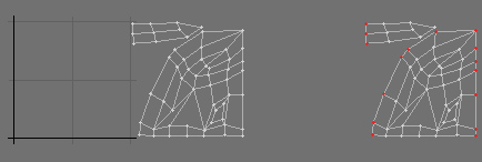
Step 8: Preparation in Modeler
Now
we've done all that we need to do a little tweaking in LW. Since
you can't select which UV segment to use for a particular image, we
need to separate the Texture UV map we've already created, into the
head and body UV's. The quickest way to do this is to unweld (ctrl-u)
all the points of your object, then select the polygons of the two
halves of your body and Maps>General>Edit
maps>Copy
Vertex map and give it a name like 1-bodyUV. You unweld first to avoid
any points which are shared by the head and body having their head UV's
copied over to the new map. Do the same for the head, calling it
2-headUV for example, and you should have two maps, one with all the
head polys on, and one with all the body polys on.
Merge your object back together, and turn it into a subpatch object. Save it, and export it to Lightwave Layout.
Step 9:Displacements
First of all you're going to need two plugins. They are available here:http://lynx.aspect-design.de/plugins/normal_displace_info.htm
http://lynx.aspect-design.de/plugins/tiff16bps.htm
The Tiff loader is needed to load the images we have created, since LW doesn't ship with a native 16 bit tiff loader. You can use the Major/Minor 88 displacement saver types if you don't want to use this loader, but it's free, so you might as well :)
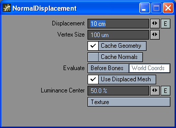
The Normal Displacement plugin is a bit like the LW native Normal Displacement plugin, but it quite a lot quicker, which is useful with the amount of polys we'll be getting up to.
In the Properties panel for your object, add the plugin called NormalDisplacement NOT Normal Displacement (with a space) as this is the slow LW one.
Open up the interface of the plugin.
Step10: Set up your maps
Go into the Texture panel of the plugin.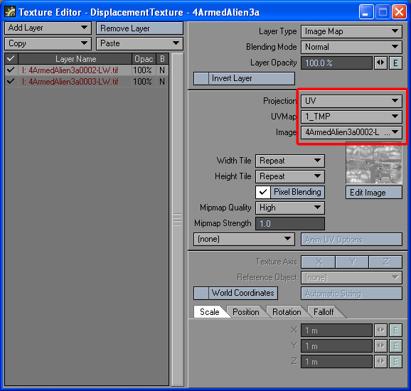
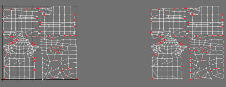
Add two image textures, and load in both of the maps you have created (Zbrush actually made 4 maps, one for each segment, but since I'm using the same map for both left and right, I'll just need the two more complex maps, since I only really drew on one half of the creature). Select the corresponding UV map for that part of the creature, and you'll have some thing like this:
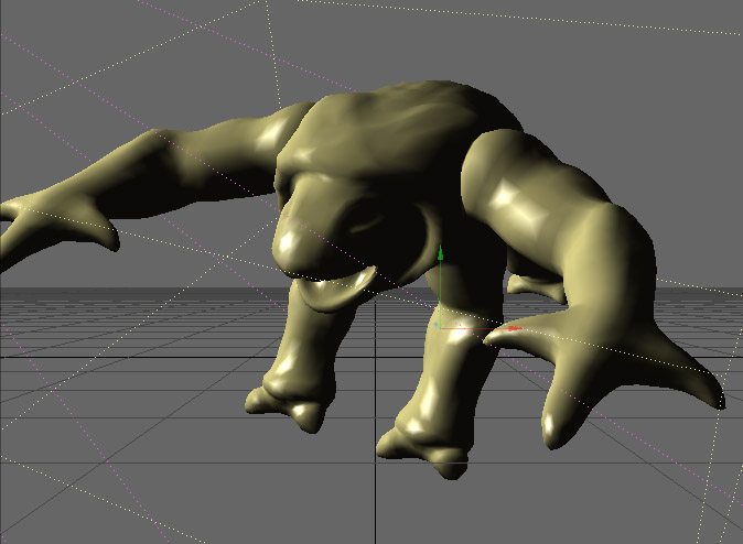
Not terrible exciting is it? Well go into the Geometry tab of your object's Properties panel, and push the Subdivisions up to 20 or so, depending on how brave you're feeling.
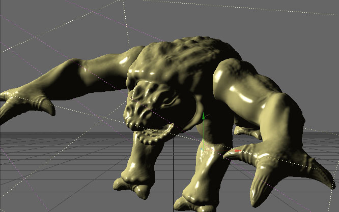
Suddenly much better but a little slower! You can use the displacement map as a bump map too, to get the finer details, or bump up the subdivisions even higher if your pc is fast enough.